Package Contents
 |
|---|
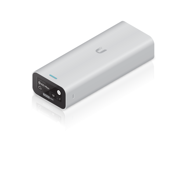
| UniFi Cloud Key Gen2 |
System Requirements
- Mobile App: Latest version of the UniFi App (available on the App Store® and Google Play™).
- Web Browser: Latest Google Chrome browser (Other browsers may have limited functionality.)
Hardware Overview
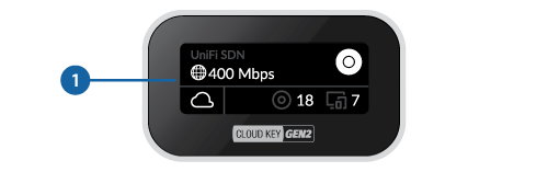

LCD Screen |
|
|---|---|
|
UniFi Network Controller name |
|
Current WAN bandwidth usage |
|
Status of Network Cloud Access |
|
Number of managed UniFi Access Points |
|
Number of client devices on the network |

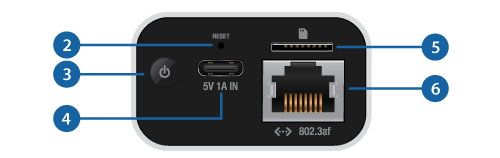
Reset Button |
|
The Reset Button serves two functions:
|
|

Power Button |
|
Press to turn the Cloud Key Gen 2 on or off. |
|

USB Type C Power Port |
|
Used for power if PoE is not available. Quick Charge 2.0 or Quick Charge 3.0-compliant USB power adapter is required. |
|

microSD Slot |
|
Optional slot used for external backup (microSD card not included). |
|

Ethernet Port |
|
Connects to a gigabit switch port on your LAN. Power can be provided by an 802.3af PoE switch, such as the UniFi PoE Switch. |
|

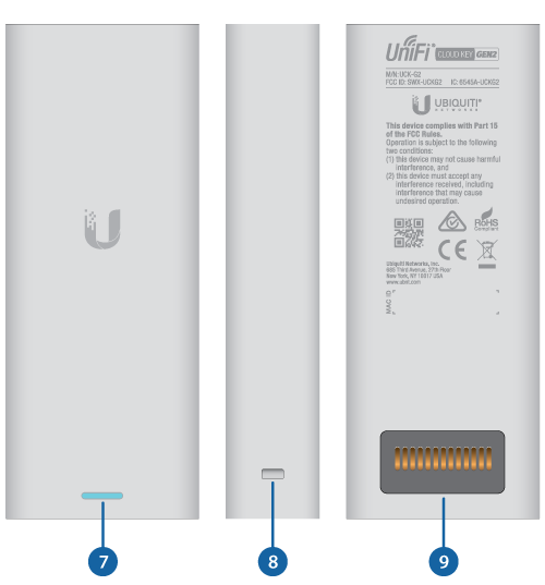

LED |
|
|---|---|
White |
Device is ready to be configured |
Flashing White |
Device is booting up Device is initializing/deinitializing |
Heartbeat White |
Firmware update in process |
Blue |
Device is configured and ready |
Flashing Blue |
Main power has been lost and device is counting down. If power is restored within 10 seconds, the device will return to its previous state. If power is not restored within 10 seconds, the device will safely shutdown. |
Slow Flashing Blue |
Client connected to device via Bluetooth (BLE) |
Flashing White/Blue |
Device is in recovery mode. The LED will cycle through a pattern at one-second intervals, between off, white, and blue. |

Rack-Mount Notch |
|
Secures the Cloud Key Gen2 into the docking bay of the optional Rackmount Accessory, model CKG2-RM (sold separately). The Rackmount Accessory allows you to install the Cloud Key Gen2 in a standard 19" rack. |
|

13-Pin Connector |
|
Connects the Cloud Key Gen2 to the optional Rackmount Accessory, model CKG2-RM (sold separately). The CKG2-RM has a docking bay for the Cloud Key Gen2 and allows you to install it in a standard 19" rack. |
|
Hardware Installation
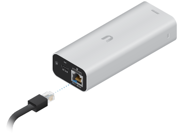
Powering the UniFi Cloud Key
Use an 802.3af-compliant switch, such as a UniFi PoE Switch, or a USB power source (not included).
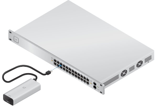
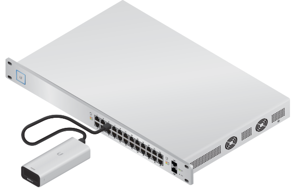
UniFi Switch
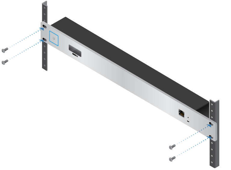
Optional Rackmount Accessory
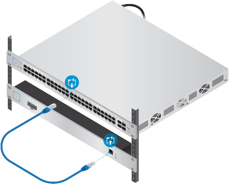
- Insert the Cloud Key Gen2 into the docking bay once the following three conditions are met:
- The 13-pin connector is face up
- The LCD screen is face forward
- There is no Ethernet cable connected to the Ethernet Port on the Cloud Key Gen2

|
|
Warning: To prevent creating a loop or other unfavorable behavior on the network, only one Ethernet connection should be used. Do not use the Ethernet port on the Cloud Key Gen2 and the Rackmount Accessory simultaneously. |
|---|

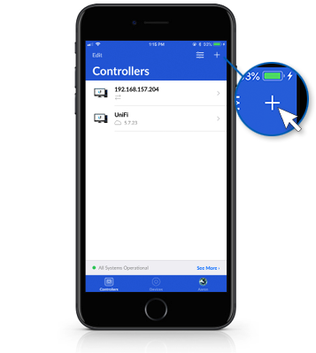
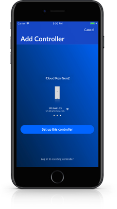
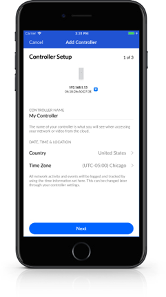
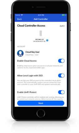
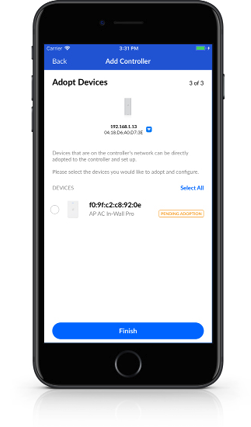
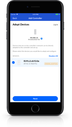
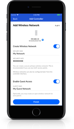
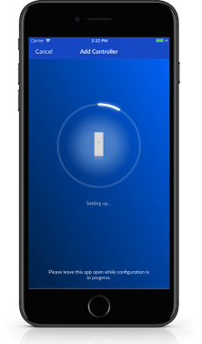
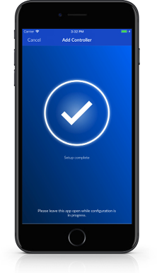
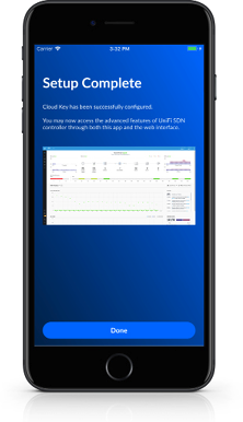
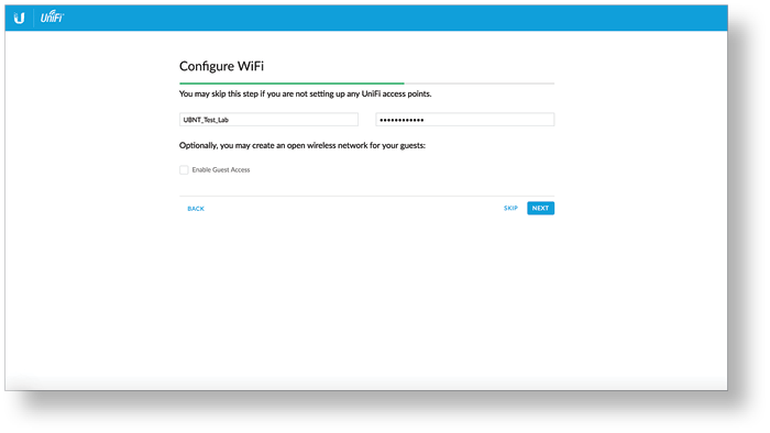
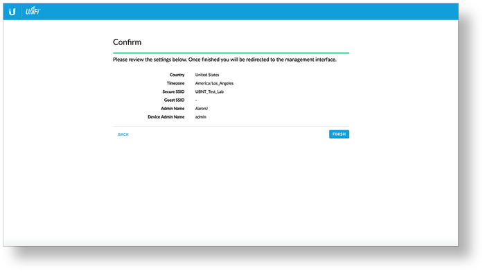
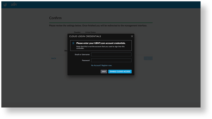
Setting Up UniFi Network via App
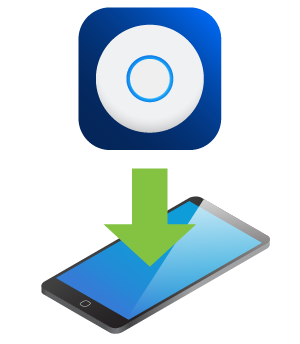
![]()
![]()
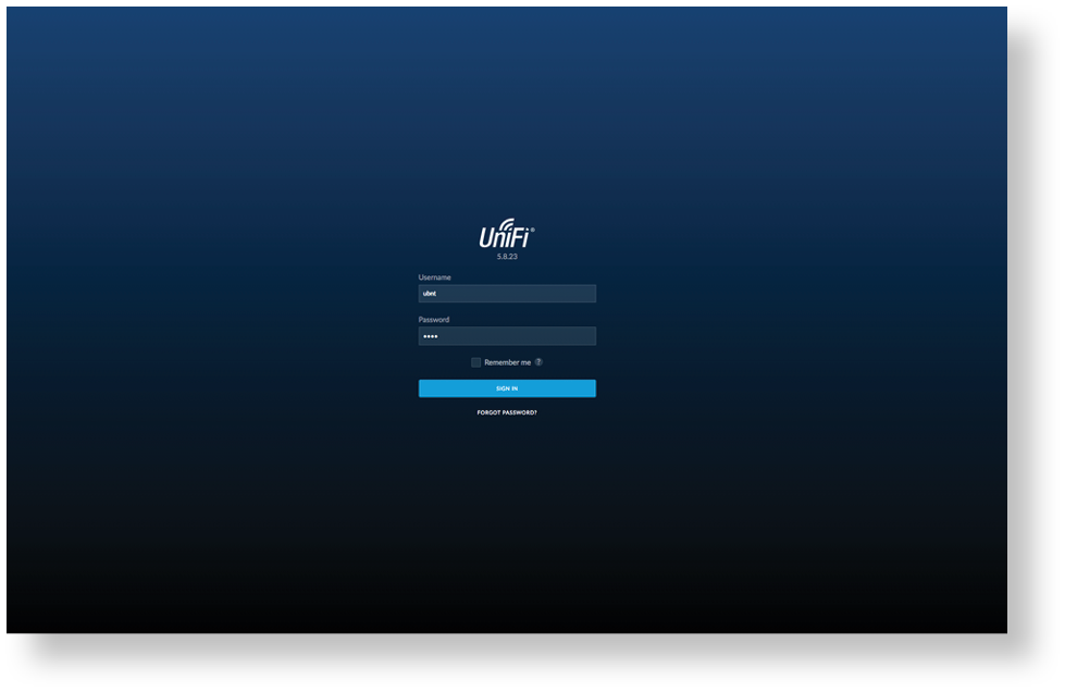
Chrome Instructions
Use the Chrome web browser to set up your Cloud Key Gen2.
- Ensure that your host system is on the same Layer-2 network as the Cloud Key Gen2.
- Launch the Chrome web browser and type the IP address of your Cloud Key Gen2 into the address field. Press enter (PC) or return (Mac).

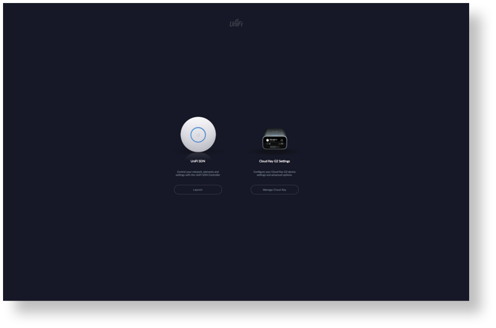
| Note: The IP address of your controller can be found on the front panel LCD of your Cloud Key Gen2. |
|---|

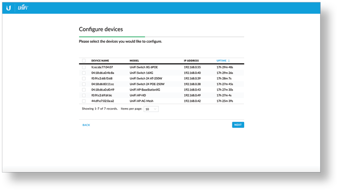
Setting Up UniFi Network
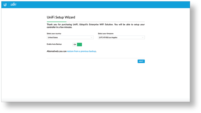
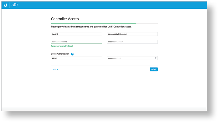
Accessing UniFi Network

Controller Sections
|
Icon |
Description |
|
|
The Dashboard screen provides a visual overview of your network’s status, including latency and throughput information for each client and device. |
|
|
The Statistics screen provides a visual representation of the clients and network traffic on your managed UniFi Network network. |
|
|
The Map section allows you to create maps (either upload custom images of your location(s) or use Google Maps™) for a visual representation of your Network network and also view your system topology. |
|
|
The Devices screen displays a list of UniFi devices managed by your Network controller. |
|
|
The Clients screen displays a list of clients connected to UniFi devices managed by your Network controller. |
|
|
The Insights screen lists detailed information about local and surrounding wireless networks, client and device statistics, security and connection detail, and other controller access information. |
|
|
The Release Notes window provides information and details on the incorporated changes and/or updates to the latest UniFi Network controller software. |
|
|
The Events screen provides a list of all events and activity taking place on your network, including errors and warnings. |
|
|
The Alerts window provides a list of alerts and events occurring on your network. |
|
|
The Settings screen provides detailed information about your UniFi Network controller and allows you to add/change/update the site configuration. |
|
|
The Live Chat Support screen provides access to a UniFi professional support representative available via live chat 24/7. |
Specifications
|
UCK-G2 |
|
|
Dimensions |
27.10 x 46.80 x 119.75 mm |
|---|---|
|
Weight |
172 g (6.07 oz) |
|
Enclosure |
Aluminum |
|
Management Interface |
UniFi App; UniFi Controller |
|
Networking Interface(s) |
(1) 10/100/1000 Ethernet Port |
|
Buttons |
(1) Power; (1) Reset to Defaults |
|
Power Supply |
802.3af PoE or USB-C 5VDC, Minimum 1A |
|
Max. Power Consumption |
5W |
|
Operating Temperature |
0 to 35° C |
|
Operating Humidity |
20 to 80% Noncondensing |
|
Certifications |
CE, FCC, IC |
Safety Notices
- Read, follow, and keep these instructions.
- Heed all warnings.
- Only use attachments/accessories specified by the manufacturer.
| WARNING: Do not use this product in location that can be submerged by water. |
|---|

| WARNING: Avoid using this product during an electrical storm. There may be a remote risk of electric shock from lightning. |
|---|
Electrical Safety Information
- Compliance is required with respect to voltage, frequency, and current requirements indicated on the manufacturer’s label. Connection to a different power source than those specified may result in improper operation, damage to the equipment or pose a fire hazard if the limitations are not followed.
- There are no operator serviceable parts inside this equipment. Service should be provided only by a qualified service technician.
Limited Warranty
The limited warranty requires the use of arbitration to resolve disputes on an individual basis, and, where applicable, specify arbitration instead of jury trials or class actions.
Compliance
FCC
Changes or modifications not expressly approved by the party responsible for compliance could void the user’s authority to operate the equipment.
This device complies with Part 15 of the FCC Rules. Operation is subject to the following two conditions.
- This device may not cause harmful interference, and
- This device must accept any interference received, including interference that may cause undesired operation.
This equipment has been tested and found to comply with the limits for a Class A digital device, pursuant to part 15 of the FCC Rules. These limits are designed to provide reasonable protection against harmful interference when the equipment is operated in a commercial environment. This equipment generates, uses, and can radiate radio frequency energy and, if not installed and used in accordance with the instruction manual, may cause harmful interference to radio communications. Operations of this equipment in a residential area is likely to cause harmful interference in which case the user will be required to correct the interference at his own expense.
This radio transmitter has been approved by FCC.
ISED Canada
CAN ICES-3(A)/NMB-3(A)
This device complies with ISED Canada licence-exempt RSS standard(s). Operation is subject to the following two conditions:
- This device may not cause interference, and
- This device must accept any interference, including interference that may cause undesired operation of the device.
This radio transmitter has been approved by ISED Canada.
CAN ICES-3(A)/NMB-3(A)
Le présent appareil est conforme aux CNR d’ISDE Canada applicables aux appareils radio exempts de licence. L’exploitation est autorisée aux deux conditions suivantes :
- l’appareil ne doit pas produire de brouillage;
- l’appareil doit accepter tout brouillage radioélectrique subi, même si le brouillage est susceptible d’en compromettre le fonctionnement.
Le présent émetteur radio a été approuvé par ISDE Canada.
IMPORTANT NOTE
Radiation Exposure Statement
- This equipment complies with radiation exposure limits set forth for an uncontrolled environment.
- This equipment should be installed and operated with minimum distance 20 cm between the radiator and your body.
- This transmitter must not be co-located or operating in conjunction with any other antenna or transmitter.
AVIS IMPORTANT
Déclaration sur l’exposition aux rayonnements
- Cet équipement est conforme aux limites prévues pour l’exposition aux rayonnements dans un environnement non contrôlé.
- Lors de l’installation et de la mise en fonctionnement de l’équipement, assurez-vous qu’il y ait une distance minimale de 20 cm entre l’élément rayonnant et vous.
- Cet émetteur ne doit être installé à proximité d’aucune autre antenne ni d’aucun autre émetteur, et ne doit être utilisé conjointement à aucun autre de ces appareils.
Australia and New Zealand
| Warning: This equipment is compliant with Class A of CISPR 32. In a residential environment this equipment may cause radio interference. |
|---|

Brazil
| Nota: Este equipamento não tem direito à proteção contra interferência prejudicial e não pode causar interferência em sistemas devidamente autorizados. |
|---|
.png)
CE Marking
CE marking on this product represents the product is in compliance with all directives that are applicable to it.
![]()
Country List | ||||||||||||||||||||||||||||||||
| ||||||||||||||||||||||||||||||||
BFWA (Broadband Fixed Wireless Access) members noted in blue |
| Note: This device meets Max. TX power limit per ETSI regulations. |
|---|
The following apply to products that operate in the 5 GHz frequency range:
| Note: This device is restricted to indoor use only when operating in the 5150 - 5350 MHz frequency range within all member states. |
|---|
| Note: All countries listed may operate at 30 dBm. BFWA member states may operate at 36 dBm. |
|---|
| Note: Operation in the 5.8 GHz frequency band is prohibited in BFWA member states. Other countries listed may use the 5.8 GHz frequency band. |
|---|